Cutting/engraving material with the ShopBot
Written on August 24th, 2023 by Laura Weller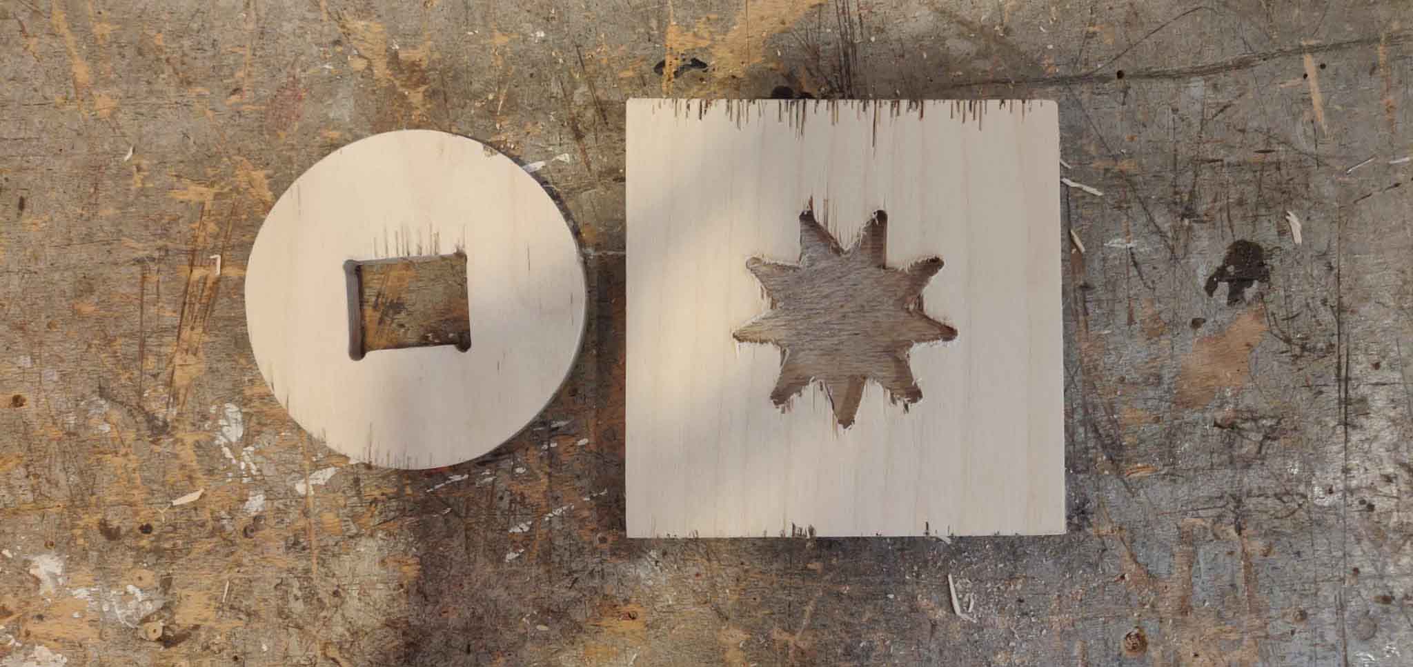
Making a design to cut or engrave
To start with the ShopBot you need a design to cut/engrave. To start with your design you need to think about 2 important things:
- which bit you are going to use and take measurements of your bit. If your design is too deep and your milling bit is not long enough, the collet and nut of the machine will touch the material. This can hurt the machine. Next you need to take into account the diameter of your bit. Often, the smaller the diameter, the shorter your bit. So, measure the bit to see what the limit is. Make sure that in your design the max depth is 1 mm or 2 mm lower then your bit length (and with bit length I do not mean total bit length but the length of the bit when it’s connected to the collet).
- If you are making a design with multiple ,milling bits, you need to have multiple projects in v-carve. One for each milling bit.
- The size of the bed is 1.22 2.44. Your design cannot be larger then this. I recommend to make it even a it smaller, just in case.
In this documentation I have used a bit of 5 mm diameter and 30 mm extracted part from the head of the machine and a material of 45 x 40 x 1,2 cm
- When you have your design created in for example illustrator you can save this and put it on a USB
- Open V carve on the computer
- Measure your material (we had 45 x 40 x 1,2 cm)
- In open V carve you create a new file where you specify the sizes of your material. Make sure that the z zero on the bottom of the material is.
- Now you can import a vectorized file. See image to see all the files the machine works with.

- When imported the vectorized file you go to toolpath (right upper side screen)
- With every file you have an order of tools that you use: drilling toolpath, pockets/engraving, inner profile cutting, outer profile cutting. Below all these tools are explained step by step:
- Drilling toolpath: The drilling toolpath you use to make the circles for the screws to screw you material to the black base layer of the machine.
How to use

- To use the drilling toolpath you first create circles for the screws that you make.
- Now you select the drilling tool and select the circles you’ve created for the screws.
- Now you select the start depth and cut depth. You want the machine to cut in just a little for the head of the screw to end up nicely in the material. Therefore you make a cut depth of around 2/3 mm.
- On the tool list you select the right material by clicking on select. Now you click ok on the right material and if you want to edit it afterwards, now click edit. Don’t do it while looking at the “select screen” since that would mess up the properties of the database. Now that you are in the edit mode, you can change the pass depth and stepover as you like. The lower the stepover the smoother the material. (0 stepover is drilling on the exact same spot again)
- The spindle speed is the rotations per minute of the head. For wood 18000 is good, for foam 9000/12000 is recommended.
- Plunge rate is the speed of the bit that is going down. Keep it on 20.
- Use vector selection order will make the machine keep the order of how you selected the round for the circles.
- Pocket toolpath: The pocket toolpath is used for engraving the material
How to use

- Here you choose the start depth and cutting depth
- Then you choose the same tool as the drilling toolpath
- Then you can decide how the pocket can be drilled by changing the clear pocket. Try out some stuff, every time you press calculate you see things changing. You can also change the pocket allowance.
- Use vector selection order will make the machine keep the order of how you selected the shapes that need to e engraved.
- Inner profile: These are the inner cuts that you can make in a material. For example a square within a circle.
How to use

- Here again you can change the start and cut depth.
- You can select a tool again.
- Now you can change the machine vectors: inner cuts on the inside of the shape, outer cuts on the outside of the shape (inner profile = inner cuts; outer profile = outer cuts). Keep the direction on climb.
- It is important look at the tabs (see image). You need to add a tab. A tab is a part that skips a bit of drilling the path to make sure that the inner part of the material stays connected to the outer part of the material to prevent the inner part from moving once it is cut. They are basically little britches to hold your final piece to the drop material.
- Outer profile: These are the outer cuts that you can make in a material. For example a circle with a sqaure in it.
How to use
- Here again you can change the start and cut depth.
- You can select a tool again.
- Now you can change the machine vectors: inner cuts on the inside of the shape, outer cuts on the outside of the shape (inner profile = inner cuts; outer profile = outer cuts). Keep the direction on climb.
- It is important look at the tabs (see image). You need to add a tab. A tab is a part that skips a bit of drilling the path to make sure that the inner part of the material stays connected to the outer part of the material to prevent the inner part from moving once it is cut. They are basically little britches to hold your final piece to the drop material.
- Now you can move to the 3D view and ask for a preview. The computer shows you what it will do.
- Once you are happy with the preview you can save the toolpath. Make sure that you save 2 seperate files: one with the drilling toolpath and one with the pockets, inner profile and outer profile toolpaths.
Cutting and or engraving your design
Before you do anything with the machine, here an overview of the basic things in the machine

- Before tuning on the machine you need to clear the space around it
- Then you turn on the computer
- Turn on the shopbot (red switch on the side -> not the red button that you can press, this is only for emergencies.)
- Now open the shopbot software on the computer
- close the preview window and press k to show the keypad
- On the Shopbot, the long edge is the x-axis and short edge is y-axis
- With the arrows on the keypad you can control the machine: arrows is x- and y-axis and page up and page down button can control the z-axis.
- Now you need to make sure that the bit in your machine is the right size.
How to replace the bit:
- Lower the skirt of the dust extraction by unscrewing the butterfly screw: not fully, just a little. (see image below)

- Take the key out of the side of the machine and unscrew the head (see image below)

- When the head is unscrewed, you need to take out the bit and see which size it is. Now grab the correct bit size and put the bit that was in back in the box.
- Seperate the collet and nut by pushing the collet out of the nut. Undo them from sawdust by knocking them on the wood. Now choose the collet that fits your bit (5 mm fits 5 mm, 6 fits 6, etc.) (see image below for the box with all the collets)

- Now put the collet in the nut and then the milling bit in the collet. If you push the collet in the nut, you can hear a click. Now you put in the milling bit correctly. Make sure that the grip between the collet and the bit is maximized. You can check this by making sure that the milling bit is fully in smaller part inside the collet. If you look top down inside the nut & collet you can see after 2 cm a spot where the inner circle of the collet becomes smaller. The end of your bit needs to align with that.
- Now you can also understand that you need to take into account the size of your milling bit. If your design is too deep and your milling bit is not long enough, the head will touch the material. This can hurt the machine. Next you need to take into account the diameter of your bit. Often, the smaller the diameter, the shorter your bit.
- Now measure the bit to see what the limit is. Make sure that in your design the max depth is 1 mm or 2 mm lower then your bit length.
- Now you screw the head (collet, nut and bit) back to the machine and you put back the dust extractor.
-
Once the bit is replaces you need to zero the Z-axes. This you do by taking the metal plate and letting the metal touch the bit. If the little green light on your computer on number 1 input, lights up green (see image) then you can put the metal plate underneath the bit on the black surface. Now you press on the computer Zero Z (on one of the top positions in the Shopbot software) and the machine moves down. Put the metal plate back into the holder. You have now your z-axis on zero.

- Move the machine to absolute 0 y clicking on the computer in the shopbot software on Zero x-y (one of the top options).
-
Now by using the arrows you can change the position of the x and y axes to what you want. Think about your origin point that you’ve set up in the beginning. Once you are happy with the origin point on the machine you click zero > zero (2) axes (see image). Now whenever you want the shopbot to move back to the position that you’ve set you click jog home (one of the top options).

- When you have done this you put on safety glasses and headphones
-
When you have don this you have to turn on the ventilation and the drilling bit. The ventilation you turn on by moving to the back room and turning it on by using the green switch. The drilling bit you turn on by turning the key on the right side. Now check by looking if the bit is not going crazy (if the bit moves around very heavily and is not centred something went wrong). On the yellow box underneath the machine you can change the RPM.

- Now you load the drilling toolpath file that you saved into the shopbot software. Now you press start and ok. Now the machine will start drilling the holes for your screws only (it does the drilling toolpath - if you saved it correctly via V carve).
- When done drilling you turn of the bit and the ventilation. You press k on the machine and now you move the bit away from the material. Now you grab a drill and drill the material stuck to the black underlayer. Make sure that in this time you do not move the material from the surface.
- Now you load the new file with all your pocket toolpaths, inner profiles and outer profiles, turn on the ventilation, turn on the bit and press start and ok. Stay close to the machine to check whether it is going allright.
- When you are done with the drilling turn off the bit and the ventilation. Move the bit away from the material by clicking k on the computer and navigating it with the arrows. Now you unscrew the material and finish it with the tools at the toolstable.
Below you can see my result:

If anything is not going to plan:
- Press spacebar and turn the key to stop the bit from spinning. Now the machine is on pause. You can fix what you want and then turn the key again and click on resume and ok.
- If you are drilling a screw, press the big red button underneath and throw the dust bag in the dust room out of the window.